| Vertical System | |
| Analog Bandwidth @ 50 Ω (-3 dB) | 1 GHz |
| Rise Time (typical) | 300 ps |
| Input Channels | 4 |
| Bandwidth Limiters | 20 MHz; 200 MHz |
| Input Impedance | 1 MΩ || 20 pF (10 MΩ || 9.5 pF using PP007 probe) |
| Input Coupling | 50 Ω: DC, 1 MΩ: AC, DC, GND |
| Maximum Input Voltage | 50 Ω: 5 Vrms, 1 MΩ: 250 V max. (Peak AC: <= 10 kHz + DC) |
| Input Connector | ProBus/BNC |
| Channel-Channel Isolation | > 40 dB @ < 100 MHz (> 30 dB @ full bandwidth) |
| Vertical Resolution | 8 bits; up to 11 with enhanced resolution (ERES) |
| Sensitivity | 50 Ω: 2 mV/div–1 V/div fully variable; 1 MΩ: 2 mV–10 V/div fully variable |
| DC Gain Accuracy | ±1.0% of full scale (typical); ±1.5% of full scale, >=10 mV/div (warranted) |
| Offset Range | 50 ½: ±400 mV @ 2–4.95 mV/div ±1 V @ 5–100 mV/div ±10 V @ 102 mV/div–1 V/div 1 M½: ±400 mV @ 2–4.95 mV/div ±1 V @ 5–100 mV/div ±10 V @ 102 mV/div–1 V/div ±100 V @ 1.02 V/div–10 V/div |
| Offset Accuracy | ±(1.5% of offset value + 0.5% of full scale +1 mV) all fixed gain setting < 2 V/div ±(1.5% of offset value + 1.0% of full scale + 1 mV) for variable and V/div settings ³ 2 V/div |
| Horizontal System | |
| Timebases | Internal timebase common to all input channels; an external clock may be applied at the auxiliary input |
| Time/Division Range | Real time: 200 ps/div – 10 s/div, RIS mode: to 20 ps/div, Roll mode: up to 1,000 s/div |
| Clock Accuracy | <= 5 ppm @ 25 °C (<= 10 ppm @ 5–40 °C) |
| Time Interval Accuracy | Clock Accuracy + Jitter |
| Trigger and Interpolator Jitter | <= 3 ps rms (typical) |
| Sample Rate and Delay Time Accuracy | Equal to Clock Accuracy |
| Channel-Channel Deskew Range | ±9 x time/div setting, 100 ms max., each channel |
| External Sample Clock | DC to 1 GHz; 50 Ω, (limited BW in 1 MΩ), BNC input, limited to 2 Ch operation (1 Ch in WR6051A), (minimum rise time and amplitude requirements apply at low frequencies) |
| Roll Mode | User selectable. Available at lower time/div settings |
| Acquisition System | |
| Single-Shot Sample Rate/Ch | 5 GS/s |
| Interleaved Sample Rate (2 Ch) | 10 GS/s |
| Random Interleaved Sampling (RIS) | 200 GS/s |
| Maximum Trigger Rate | 125,000 waveforms/second |
| Intersegment Time | 8 µs |
| Acquisition Memory Options - Standard (4 Ch / 2Ch) | 4M/8M |
| Acquisition Memory Options - Option L (4 Ch / 2Ch) | 8M/16M |
| Acquisition Memory Options - Option VL (4 Ch / 2Ch) | 12M/24M |
| Sequence Time Stamp Resolution | 1 ns |
| Segments (Sequence Mode) - Standard | 1000 |
| Segments (Sequence Mode) - Option L | 5000 |
| Segments (Sequence Mode) - Option VL | 10000 |
| Acquisition Processing | |
| Averaging | Summed and continuous averaging to 1 million sweeps |
| Enhanced Resolution (ERES) | From 8.5 to 11 bits vertical resolution |
| Envelope (Extrema) | Envelope, floor, or roof for up to 1 million sweeps |
| Interpolation | Linear or Sinx/x |
| Time Resolution (min, Single-shot) | 100 ps (10 GS/s) |
| Triggering System | |
| Trigger Modes | Normal, Auto, Single, Stop |
| Sources | Any input channel, External, Ext/10, or Line; slope and level unique to each source, except Line |
| Coupling | DC |
| Pre-trigger Delay | 0–100% of memory size (adjustable in 1% increments, or 100 ns) |
| Post-trigger Delay | Up to 10,000 divisions in real time mode, limited at slower time/div settings in roll mode |
| Hold-off by Time or Events | 2 ns to 20 s or 1 to 1,000,000,000 events |
| Internal Trigger Range | ±4.1 div from center (typical) |
| Trigger Sensitivity with Edge Trigger (Ch 1–4) | 2 div @ < 1 GHz, 1 div @ < 750 MHz |
| External Trigger Input Range | EXT/10 ±4 V; EXT ±400 mV |
| Max. Trigger Frequency, SMART Trigger | 750 MHz @ >= 10 mV |
| Trigger Level DC Accuracy | ±4% full scale ±2 mV (typical) |
| Basic Triggers | |
| Edge | Triggers when signal meets slope (positive or negative) and level condition. |
| Logic (Pattern) | Logic combination (AND, NAND, OR, NOR) of 5 inputs (4 channels and external trigger input – 2 Ch+EXT on WR6051A). Each source can be high, low, or don’t care.The high and low level can be selected independently. Triggers at start or end of the pattern. |
| SMART Triggers | |
| State or Edge Qualified | Triggers on any input source only if a defined state or edge occurred on another input source. Delay between sources is selectable by time or events. |
| Dropout | Triggers if signal drops out for longer than selected time between 2 ns and 20 s. |
| SMART Triggers with Exclusion Technology | |
| Glitch and Pulse Width | Triggers on positive or negative glitches with widths selectable from 600 ps to 20 s or on intermittent faults (subject to bandwidth limit of oscilloscope). |
| Signal or Pattern Width | Triggers on intervals selectable between 2 ns and 20 s. |
| Timeout (State/Edge Qualified) | Triggers on any source if a given state (or transition edge) has occurred on another source. Delay between sources is 2 ns to 20 s, or 1 to 99,999,999 events. |
| Exclusion Triggering | Trigger on intermittent faults by specifying the normal width or period. |
| Color Waveform Display | |
| Type | Color 8.4" flat-panel TFT-LCD with high resolution touch screen |
| Resolution | SVGA; 800 x 600 pixels |
| Number of traces | Display a maximum of 8 traces. Simultaneously display channel, zoom, memory, and math traces. |
| Grid Styles | Auto, Single, Dual, Quad, Octal, XY, Single + XY, Dual + XY |
| Waveform Representation | Sample dots joined or dots only |
| Internal Waveform Memory | |
| Internal Waveform Memory | M1, M2, M3, M4 Internal Waveform Memory (store full-length waveform with 16 bits/data point) or store to any number of files limited only by data storage media. |
| Automatic Setup | |
| Auto Setup | Automatically sets timebase, trigger, and sensitivity to display a wide range of repetitive signals. |
| Vertical Find Scale | Automatically sets the vertical sensitivity and offset for the selected channels to display a waveform with maximum dynamic range. |
| Probes | |
| Probes | One PP007-WR-1 per channel standard; Optional passive and active probes available. |
| Probe System: ProBus | Automatically detects and supports a variety of compatible probes. |
| Scale Factors | Automatically or manually selected, depending on probe used |
| Analog Persistence Display | |
| Analog and Color-Graded Persistence | Variable saturation levels; stores each trace’s persistence data in memory. |
| Trace Selection | Activate persistence on all or any combination of traces. |
| Sweep Display Modes | All accumulated, or all accumulated with last trace highlighted. |
| Persistence Selections | Select analog, color, or three-dimensional. |
| Persistence Types | Aging time select from 500 ms to infinity. |
| Processor/CPU | |
| Processor Type | Intel® Celeron,® 2.0 GHz or better. |
| Processor Memory | 256 MB on Std and M option; 512 MB with L and VL options |
| Operating System | Microsoft Windows® XP Professional |
| Zoom Expansion Traces | |
| Zoom Expansion Traces | Display up to 4 Zoom/Math traces |
| Setup Storage | |
| Setup Storage | Front Panel and Instrument Status Store to the internal hard drive, over the network, or to a USB-connected peripheral device. |
| Interface | |
| Remote Control | Via Windows Automation, or via LeCroy Remote Command Set |
| GPIB Port (optional) | Supports IEEE – 488.2 |
| Ethernet Port | 10/100Base-T Ethernet interface (RJ-45 connector) |
| USB Ports | 5 USB 2.0 ports (one on front of instrument) supports Windows-compatible devices. |
| Auxiliary Input | |
| Signal Types | Selected from External Trigger or External Clock input on front panel |
| Coupling | 50 Ω: DC, 1 MΩ: AC, DC, GND |
| Maximum Input Voltage | 50 Ω: 5 Vrms, 1 MΩ: 250 V max. (Peak AC: <= 10 kHz + DC) |
| Auxiliary Output | |
| Signal Types | Trigger Enabled, Trigger Output. Pass/Fail, or Off |
| Output Level | TTL, Å3.3 V |
| Calibrator Signal | Output available on front panel connector provides a variety of signals for probe calibration and compensation. |
| General | |
| Auto Calibration | Ensures specified DC and timing accuracy is maintained for 1 year minimum. |
| Power Requirements | 100–240 Vrms at 50/60 Hz; 115 Vrms (±10%) at 400 Hz, Automatic AC Voltage Selection Installation Category: 300V CAT II; Max. Power Consumption: 400 VA/400 W; 350 VA/350 W for WaveRunner 6051A |
| Environmental and Safety | |
| Temperature (Operating) | +5 °C to 40 °C |
| Temperature (Non-Operating) | -20 °C to +60 °C |
| Humidity (Operating) | 5% to 80% RH (non-condensing) up to 30 °C, Upper limit derates linearly to 45% RH (non-condensing) at 40 °C |
| Humidity (Non-Operating) | 5% to 95% RH (non-condensing) as tested per MIL-PRF-28800F |
| Altitude (Operating) | 3,048 m (10,000 ft.) max at<=25 °C |
| Altitude (Non-Operating) | 12,190 m (40,000 ft.) |
| Physical Dimensions | |
| Dimensions (HWD) | (HWD) 211 mm x 355 mm x 363 mm (excluding feet) 8.3" x 13.8" x 14.3" |
| Shipping Weight | less than 13.6 kg. (30 lbs.) |
| Net Weight | 10 kg. (22 lbs.), excluding printer |
| Certifications | |
| Certifications | CE Compliant, UL and cUL listed; Conforms to EN 61326-1, EN 61010-1, UL 3111-1, and CSA C22.2 No. 1010.1 |
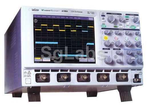
LeCroy, Waverunner 6100A
Sei in: OSCILLOSCOPI » Digitale

Le foto sono di repertorio e potrebbero non corrispondere all'oggetto realmente venduto, come pure le opzioni installate. Su richiesta verranno fornite foto in alta risoluzione e opzioni reali dell'oggetto in vendita.
Descrizione del prodotto
- Canali: 4
- Display: Color DSO
- Larghezza di Banda : 1 GHz
- Velocità di campionamento: 10 Gs/s max


