| Vertical System | |
| Analog Bandwidth @ 50 Ω (-3 dB) | 1 GHz |
| Rise Time (typical) | 300 ps |
| Input Channels | 4 |
| Bandwidth Limiters | 20 MHz; 200 MHz |
| Input Impedance | 1 MΩ || 20 pF (10 MΩ || 9.5 pF using PP007 probe) |
| Input Coupling | 50 Ω: DC, 1 MΩ: AC, DC, GND |
| Maximum Input Voltage | 50 Ω: 5 Vrms, 1 MΩ: 250 V max. (Peak AC: <= 10 kHz + DC) |
| Input Connector | ProBus/BNC |
| Channel-Channel Isolation | > 40 dB @ < 100 MHz (> 30 dB @ full bandwidth) |
| Vertical Resolution | 8 bits; up to 11 with enhanced resolution (ERES) |
| Sensitivity | 50 Ω: 2 mV/div–1 V/div fully variable; 1 MΩ: 2 mV–10 V/div fully variable |
| DC Gain Accuracy | ±1.0% of full scale (typical); ±1.5% of full scale, >=10 mV/div (warranted) |
| Offset Range | 50 ½: ±400 mV @ 2–4.95 mV/div ±1 V @ 5–100 mV/div ±10 V @ 102 mV/div–1 V/div 1 M½: ±400 mV @ 2–4.95 mV/div ±1 V @ 5–100 mV/div ±10 V @ 102 mV/div–1 V/div ±100 V @ 1.02 V/div–10 V/div |
| Offset Accuracy | ±(1.5% of offset value + 0.5% of full scale +1 mV) all fixed gain setting < 2 V/div ±(1.5% of offset value + 1.0% of full scale + 1 mV) for variable and V/div settings ³ 2 V/div |
| Horizontal System | |
| Timebases | Internal timebase common to all input channels; an external clock may be applied at the auxiliary input |
| Time/Division Range | Real time: 200 ps/div – 10 s/div, RIS mode: to 20 ps/div, Roll mode: up to 1,000 s/div |
| Clock Accuracy | <= 5 ppm @ 25 °C (<= 10 ppm @ 5–40 °C) |
| Time Interval Accuracy | Clock Accuracy + Jitter |
| Trigger and Interpolator Jitter | <= 3 ps rms (typical) |
| Sample Rate and Delay Time Accuracy | Equal to Clock Accuracy |
| Channel-Channel Deskew Range | ±9 x time/div setting, 100 ms max., each channel |
| External Sample Clock | DC to 1 GHz; 50 Ω, (limited BW in 1 MΩ), BNC input, limited to 2 Ch operation (1 Ch in WR6051A), (minimum rise time and amplitude requirements apply at low frequencies) |
| Roll Mode | User selectable. Available at lower time/div settings |
| Acquisition System | |
| Single-Shot Sample Rate/Ch | 5 GS/s |
| Interleaved Sample Rate (2 Ch) | 10 GS/s |
| Random Interleaved Sampling (RIS) | 200 GS/s |
| Maximum Trigger Rate | 125,000 waveforms/second |
| Intersegment Time | 8 µs |
| Acquisition Memory Options - Standard (4 Ch / 2Ch) | 4M/8M |
| Acquisition Memory Options - Option L (4 Ch / 2Ch) | 8M/16M |
| Acquisition Memory Options - Option VL (4 Ch / 2Ch) | 12M/24M |
| Sequence Time Stamp Resolution | 1 ns |
| Segments (Sequence Mode) - Standard | 1000 |
| Segments (Sequence Mode) - Option L | 5000 |
| Segments (Sequence Mode) - Option VL | 10000 |
| Acquisition Processing | |
| Averaging | Summed and continuous averaging to 1 million sweeps |
| Enhanced Resolution (ERES) | From 8.5 to 11 bits vertical resolution |
| Envelope (Extrema) | Envelope, floor, or roof for up to 1 million sweeps |
| Interpolation | Linear or Sinx/x |
| Time Resolution (min, Single-shot) | 100 ps (10 GS/s) |
| Triggering System | |
| Trigger Modes | Normal, Auto, Single, Stop |
| Sources | Any input channel, External, Ext/10, or Line; slope and level unique to each source, except Line |
| Coupling | DC |
| Pre-trigger Delay | 0–100% of memory size (adjustable in 1% increments, or 100 ns) |
| Post-trigger Delay | Up to 10,000 divisions in real time mode, limited at slower time/div settings in roll mode |
| Hold-off by Time or Events | 2 ns to 20 s or 1 to 1,000,000,000 events |
| Internal Trigger Range | ±4.1 div from center (typical) |
| Trigger Sensitivity with Edge Trigger (Ch 1–4) | 2 div @ < 1 GHz, 1 div @ < 750 MHz |
| External Trigger Input Range | EXT/10 ±4 V; EXT ±400 mV |
| Max. Trigger Frequency, SMART Trigger | 750 MHz @ >= 10 mV |
| Trigger Level DC Accuracy | ±4% full scale ±2 mV (typical) |
| Basic Triggers | |
| Edge | Triggers when signal meets slope (positive or negative) and level condition. |
| Logic (Pattern) | Logic combination (AND, NAND, OR, NOR) of 5 inputs (4 channels and external trigger input – 2 Ch+EXT on WR6051A). Each source can be high, low, or don’t care.The high and low level can be selected independently. Triggers at start or end of the pattern. |
| SMART Triggers | |
| State or Edge Qualified | Triggers on any input source only if a defined state or edge occurred on another input source. Delay between sources is selectable by time or events. |
| Dropout | Triggers if signal drops out for longer than selected time between 2 ns and 20 s. |
| SMART Triggers with Exclusion Technology | |
| Glitch and Pulse Width | Triggers on positive or negative glitches with widths selectable from 600 ps to 20 s or on intermittent faults (subject to bandwidth limit of oscilloscope). |
| Signal or Pattern Width | Triggers on intervals selectable between 2 ns and 20 s. |
| Timeout (State/Edge Qualified) | Triggers on any source if a given state (or transition edge) has occurred on another source. Delay between sources is 2 ns to 20 s, or 1 to 99,999,999 events. |
| Exclusion Triggering | Trigger on intermittent faults by specifying the normal width or period. |
| Color Waveform Display | |
| Type | Color 8.4" flat-panel TFT-LCD with high resolution touch screen |
| Resolution | SVGA; 800 x 600 pixels |
| Number of traces | Display a maximum of 8 traces. Simultaneously display channel, zoom, memory, and math traces. |
| Grid Styles | Auto, Single, Dual, Quad, Octal, XY, Single + XY, Dual + XY |
| Waveform Representation | Sample dots joined or dots only |
| Internal Waveform Memory | |
| Internal Waveform Memory | M1, M2, M3, M4 Internal Waveform Memory (store full-length waveform with 16 bits/data point) or store to any number of files limited only by data storage media. |
| Automatic Setup | |
| Auto Setup | Automatically sets timebase, trigger, and sensitivity to display a wide range of repetitive signals. |
| Vertical Find Scale | Automatically sets the vertical sensitivity and offset for the selected channels to display a waveform with maximum dynamic range. |
| Probes | |
| Probes | One PP007-WR-1 per channel standard; Optional passive and active probes available. |
| Probe System: ProBus | Automatically detects and supports a variety of compatible probes. |
| Scale Factors | Automatically or manually selected, depending on probe used |
| Analog Persistence Display | |
| Analog and Color-Graded Persistence | Variable saturation levels; stores each trace’s persistence data in memory. |
| Trace Selection | Activate persistence on all or any combination of traces. |
| Sweep Display Modes | All accumulated, or all accumulated with last trace highlighted. |
| Persistence Selections | Select analog, color, or three-dimensional. |
| Persistence Types | Aging time select from 500 ms to infinity. |
| Processor/CPU | |
| Processor Type | Intel® Celeron,® 2.0 GHz or better. |
| Processor Memory | 256 MB on Std and M option; 512 MB with L and VL options |
| Operating System | Microsoft Windows® XP Professional |
| Zoom Expansion Traces | |
| Zoom Expansion Traces | Display up to 4 Zoom/Math traces |
| Setup Storage | |
| Setup Storage | Front Panel and Instrument Status Store to the internal hard drive, over the network, or to a USB-connected peripheral device. |
| Interface | |
| Remote Control | Via Windows Automation, or via LeCroy Remote Command Set |
| GPIB Port (optional) | Supports IEEE – 488.2 |
| Ethernet Port | 10/100Base-T Ethernet interface (RJ-45 connector) |
| USB Ports | 5 USB 2.0 ports (one on front of instrument) supports Windows-compatible devices. |
| Auxiliary Input | |
| Signal Types | Selected from External Trigger or External Clock input on front panel |
| Coupling | 50 Ω: DC, 1 MΩ: AC, DC, GND |
| Maximum Input Voltage | 50 Ω: 5 Vrms, 1 MΩ: 250 V max. (Peak AC: <= 10 kHz + DC) |
| Auxiliary Output | |
| Signal Types | Trigger Enabled, Trigger Output. Pass/Fail, or Off |
| Output Level | TTL, Å3.3 V |
| Calibrator Signal | Output available on front panel connector provides a variety of signals for probe calibration and compensation. |
| General | |
| Auto Calibration | Ensures specified DC and timing accuracy is maintained for 1 year minimum. |
| Power Requirements | 100–240 Vrms at 50/60 Hz; 115 Vrms (±10%) at 400 Hz, Automatic AC Voltage Selection Installation Category: 300V CAT II; Max. Power Consumption: 400 VA/400 W; 350 VA/350 W for WaveRunner 6051A |
| Environmental and Safety | |
| Temperature (Operating) | +5 °C to 40 °C |
| Temperature (Non-Operating) | -20 °C to +60 °C |
| Humidity (Operating) | 5% to 80% RH (non-condensing) up to 30 °C, Upper limit derates linearly to 45% RH (non-condensing) at 40 °C |
| Humidity (Non-Operating) | 5% to 95% RH (non-condensing) as tested per MIL-PRF-28800F |
| Altitude (Operating) | 3,048 m (10,000 ft.) max at<=25 °C |
| Altitude (Non-Operating) | 12,190 m (40,000 ft.) |
| Physical Dimensions | |
| Dimensions (HWD) | (HWD) 211 mm x 355 mm x 363 mm (excluding feet) 8.3" x 13.8" x 14.3" |
| Shipping Weight | less than 13.6 kg. (30 lbs.) |
| Net Weight | 10 kg. (22 lbs.), excluding printer |
| Certifications | |
| Certifications | CE Compliant, UL and cUL listed; Conforms to EN 61326-1, EN 61010-1, UL 3111-1, and CSA C22.2 No. 1010.1 |
LeCroy, Waverunner 6100A
You are here: Oscilloscope » Digital
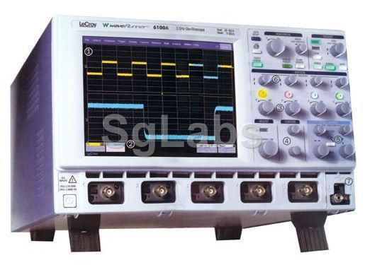
Above pictures can be different from actually sold item as well as the installed options. On request we'll send you high resolution pictures and options of the real item.
Product description
- Channels: 4
- Display: Color DSO
- BandWidth: 1 GHz
- Sampling: 10 Gs/s max


